
NJD diagram: understanding the electronics of a dub siren
If you play, buy or repair dub sirens, understanding what goes on inside gives you a serious advantage. You know what to listen for when you test a second-hand unit, you know how to modify it, you know why one model sounds different from another. This guide breaks down the typical layout of an analogue dub siren – often referred to as the ‘NJD style’ after the famous British units that popularised the architecture.
No need to be an electronics engineer: we’ll get straight to the point, step by step, explaining the role of each block.
Why do we talk about “NJD schematics”?
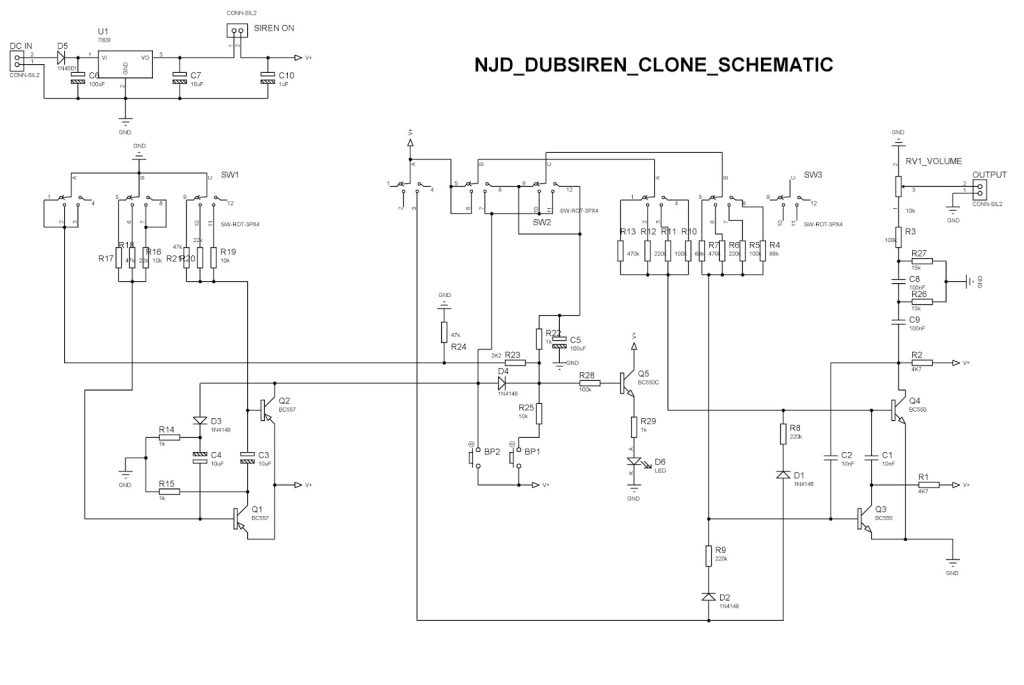
NJD Electronics, the legendary British manufacturer, has never officially published the schematics of its dub sirens (notably the SE10). But successive reverse-engineering and modifications by users have made it possible to reconstitute the reference architecture: a simple analogue design, based on two 555 timers, some signal shaping and sometimes a delay.
This architecture is now considered to be the basic pattern of the analogue dub siren. Many craftsmen (Klementz, Zongo, anonymous DIY builders) are openly inspired by it, because it’s tried and tested, robust and sounds good.
Architecture in four blocks
Any analogue dub siren breaks down into four functional stages:
[Block 1] LFO ──┐
               ↓
[Block 2] Audio oscillator ──→ [Block 3] Shaping + trigger ──→ [Block 4] Delay (optional) ──→ Output
Block 1: the LFO (Low Frequency Oscillator).
What it does
The LFO produces a very slow oscillation, typically between 0.1 Hz (one cycle every 10 seconds) and 20 Hz (twenty cycles per second). This frequency is inaudible in itself: the LFO does not produce any sound. Its job is to modulate something else – in this case, the pitch of the audio oscillator.
How it’s implemented
The central component is an NE555 timer (or its lower-power TLC555 cousin), wired in astable mode. In this mode, the 555 automatically alternates between two states (high/low) at a frequency defined by :
- A fixed resistor R1 (often 1 to 10 kΩ)
- A variable resistor R2 (the rate potentiometer)
- A large electrolytic capacitor C (10 to 100 µF, which is what makes it slow).
The formula for the frequency in astable mode :
f = 1.44 / ((R1 + 2×R2) × C)With R1 = 1 kΩ, R2 variable from 1 to 100 kΩ and C = 47 µF, you get an LFO adjustable from 0.15 Hz to around 15 Hz. This is the useful range.
Waveform produced
The 555 in astable mode generates an asymmetrical square wave by default. This is not ideal for smooth modulation, so many schemes add an RC circuit at the output to integrate this quasi-triangle or pseudo-sine square wave. The result is modulation that’s more organic, more “siren-like” and less “choppy bzz”.
Block 2: the audio oscillator
What it does
It produces the sound you hear. It generates a frequency in the audio band (typically 200 Hz to 4 kHz) which will be modulated in pitch by the LFO, creating the siren effect.
How it’s implemented
Another astable 555. But this time with :
- A fixed resistor R1
- A variable resistor R2 (the pitch potentiometer) coupled to
- Themodulation input that receives the LFO signal
- A much smaller capacitor C (10 to 100 nF) to produce audio frequencies
The modulation input: pin 5 (Control Voltage)
This is the keystone of the design. Pin 5 of the 555 is called CV (Control Voltage): its voltage controls the internal switching threshold, and therefore indirectly the frequency generated.
When the LFO oscillates slowly, its voltage varies. This voltage arrives on pin 5 of the 555 audio via a depth potentiometer (which attenuates or amplifies the amplitude of the modulation). The result: the audio frequency rises and falls with the rhythm of the LFO.
This is exactly what the ‘siren sound’ is – an audio frequency modulated by a slow frequency.
Why the 555 rather than a traditional VCO?
There are several reasons:
- Cost: a 555 costs 30 cents
- Robustness: it tolerates 5-15 V power supplies and small temporary short circuits
- Sonic character: its raw square wave, slightly noisy, slightly unstable, gives that distinctive analogue grain that dub sirens have
- Simplicity: you don’t need to be an engineer to wire it up – self-build is accessible
It’s this pragmatic elegance that has cemented the 555 in dub siren culture.
Block 3: signal shaping and triggering
The 555 output problem
The audio oscillator outputs a full-amplitude square wave – around 9 V peak-to-peak on a 9 V power supply. This is far too hot for a mixer (which expects line level, i.e. 1-2 V peak-to-peak maximum) and too rich in high harmonics to sound good.
Attenuation and filtering
So we insert :
- A voltage divider (two resistors) to bring the signal down to the correct level.
- A decoupling capacitor (10 µF at the output) to suppress the DC component
- Often a simple low-pass filter (R + C) to soften the high frequencies. With a potentiometer, this filter becomes a tone control.
The trigger (momentary push-button)
The dub siren only sounds when pressed. The trigger physically interrupts the output signal until the button is pressed. Two common implementations:
- Mute method: a transistor (or FET) cuts the output when idle, releasing it when the button is pressed.
- Reset method: the button holds pin 4 (reset) of the 555 audio at zero, the oscillator does not operate at all when idle.
The second method is more economical in terms of components and more ‘dry’ sonically – no residual tail.
Why a momentary button rather than a switch?
For the live gesture. A push button lets you play the siren like an instrument: short press for a quick blip, long press for a prolonged wail, simultaneous pitch modulation with the other hand. It’s exactly the same logic as a keyboard key on a synth.
Block 4: delay (the secret of the dub sound)
Why delay is essential
A dub siren without delay sounds clinical, flat and flat. The delay (or echo, or simulated echo tape) is what transforms a dry hit into the undulating cascade that defines the dub sound.
Three approaches to analogue/hybrid delay
The PT2399 (low-fi digital delay)
The PT2399 is a 100% digital integrated circuit – but with a character all its own: natural bandwidth limit, slight degradation at high feedback, overall ‘warm’ sound to the point where it has become a DIY audio standard. Many modern DIY dub sirens use a PT2399 delay module: €3-3 per component, 30-300 ms range, quite decent quality.
The BBD (Bucket Brigade Device)
The MN3005 and MN3007 chips are analogue sampling delays (each cell in a ‘bucket’ passes the value to the next at the rate of a clock). The sound is more organic and degrading than that of the PT2399, but the components are expensive and increasingly rare.
External delay via spring reverb / tape echo
Many top-of-the-range dub sirens – including vintage NJDs – do not include a delay and rely on the sound system chain for this: preamp with tape echo, spring reverb on send, etc. This is the ‘pure’ choice. This is the ‘pure’ choice: the siren remains a minimal instrument, the effect lives in the ecosystem.
Feedback: the magic parameter
On any delay, feedback (reinjection of the output into the input) creates repetition. At 30-40% you get 3-4 repeats that fade away. At 70-80% the repeats last a long time. Above 90%, the delay goes into self-oscillation: it generates its own sound, without the siren being pressed. This is the “pumping up the delay” effect we hear so much in dub.
The complete diagram (overview)
Here’s the block diagram for an NJD-style dub siren with PT2399 delay:
                ┌──────────────┐
   9V battery ──→ │ Control │ ──→ +9V stable to all blocks.
                 └──────────────┘

   ┌──────────┐ ┌─────────────┐
   │ 555 LFO │─── via depth ─→│ pin 5 (CV) │
   │ (rate) │ │ 555 audio │
   └──────────┘ │ (pitch) │
                                └──────┬──────┘
                                       │ pin 3 (out)
                                       ↓
                              ┌────────────────┐
                              │ Trigger button │
                              │ (mute) │
                              └────────┬───────┘
                                       ↓
                            ┌──────────────────┐
                            │ Divisor + Cap │
                            │ (attenuation) │
                            └────────┬─────────┘
                                     ↓
                            ┌──────────────────┐
                            │ Module delay │
                            │ PT2399 (time + │
                            │ feedback) │
                            └────────┬─────────┘
                                     ↓
                                  Volume
                                     ↓
                                  Jack out
Typical values:
- LFO: R1 = 1k, R2 = 100k (pot rate), C = 47 µF
- Audio: R1 = 4.7k, R2 = 10k (pot pitch), C = 100 nF
- Depth: 100 kΩ pot between LFO and pin 5 of 555 audio
- Output: 10k / 4.7k divider, 10 µF decoupling cap
- Delay: standard PT2399 module, 50k pot time, 50k pot feedback
Common variants
Dual-oscillator (NJD SE10 style)
The SE10 is known for its rich sound: this is partly because it has two mixed audio oscillators, either in parallel (giving harmonic beats) or one modulating the other (FM). To reproduce this, simply double the 555 audio block and sum the outputs with two resistors before block 3.
Pitch tracking between LFO and oscillator
On some units, the LFO can be synchronised to the trigger trigger (it restarts from zero each time it is pressed), giving more ‘rhythmic’ sirens. Implementation: use pin 4 (reset) of the 555 LFO in parallel with the trigger.
Shape variants
Some designs add a waveform switch to the LFO or audio: with a few diodes and resistors at the output of the 555, you can transform a square wave into a triangle, a pseudo-saw or an asymmetric pulse. More sonic variety, more siren patterns.
What’s all this really for?
Buying second-hand
Knowing the schematic helps you diagnose a unit:
- The pitch no longer changes → potentiometer R2 on the 555 audio dead
- The LFO no longer works → 555 LFO burnt out, or timing capacitor blown out
- The trigger doesn’t mute properly → faulty mute transistor or bouncing knob
- The delay slips → 555 audio OK but PT2399 module damaged
With a schematic in mind, you can ask the seller the right questions and negotiate with full knowledge of the facts.
Modifying your dub siren
Many classic mods become obvious when you know the schematic:
- Add a second LFO for complex modulations
- Extend the pitch range by changing the C capacitor on the 555 audio (smaller = higher, larger = lower)
- Add a CV in to drive the siren from a modular sequencer
- Replace the PT2399 with a BBD to make it more organic
To make your own
If you’re into DIY, see our step-by-step tutorial for building a dub siren. The diagram above is just the basics.
Resources for further reading
- NE555 datasheet: read it at least once to understand the monostable, astable and bistable modes.
- PT2399 datasheet: for delay implementations
- DIY audio forums (diyAudio, electro-music, freestompboxes): you’ll find in-depth analyses of dub siren schematics, free PCBs and photos of dismantled vintage units.
- Sound System Forum: active technical section, lots of connoisseurs
In a nutshell
The typical layout of an analogue dub siren consists of four blocks: a 555 LFO, a 555 audio oscillator modulated by the LFO, trigger shaping and a delay (often PT2399 in modern DIY). This architecture, popularised by the British NJDs, has become the reference in the field. Understanding how it works transforms you from a passive user into a musician-technician capable of judging, modifying or building your own instrument.
If you’re itching to put it into practice, read our DIY tutorial – it applies step by step the schema described here.
Thanks for reading, I hope this article was helpful!
🙏 If you enjoyed it, please share on your social networks 🙏
And if you have any remarks, thoughts, experiences or arguments to share:
Feel free to share in the comments below!