
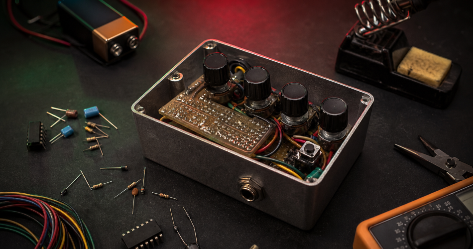
How to build a DIY dub siren: step-by-step tutorial
Building your own dub siren is almost a rite of passage in sound system culture. The project is accessible – you don’t need to be an engineer – and the result is a unique instrument that can be modified at will, costing you between €30 and €60 worth of components. This tutorial guides you through a classic assembly based on the NE555, the legendary timer found in most home-made dub sirens.
When you’re finished, you’ll have a working unit with adjustable siren, optional analogue delay and line output ready to plug into your mixer.
Why make your own dub siren?
Before you get started, you need to know what you’re getting into.
Good reasons:
- Understand audio electronics by doing
- Have a unique object with your box, your buttons, your sound
- Save money: €50 worth of components compared with €300 for a commercial unit
- Being able to modify, hack and improve your instrument
- The tactile satisfaction of playing a machine you’ve built yourself
The real reasons to avoid :
- You’ve never soldered before and don’t have the time to learn
- You want something that works straight away, without trial and error
- You don’t have any basic equipment (soldering iron, multimeter)
If you’re in the second of these situations, look for a pre-assembled kit or a second-hand Benidub unit.
Another option: a machine that already has the siren built in, along with the delay and the mixer, such as the KLEMENTZ Dub Mixer.
The equipment you need
Tools
- Soldering iron (25-40 W) and tin
- Cutting pliers and fine pliers
- Multimeter
- Screwdriver (Phillips + flat)
- Drill (for drilling the casing)
- Optional but useful: soldering station, third hand, desoldering pump
Electronic components
Here is the list for a single-oscillator assembly with LFO:
| Component | Quantity | Detail |
|---|---|---|
| NE555 (or TLC555) | 2 | one for the audio oscillator, one for the LFO |
| DIP-8 support | 2 | to avoid soldering directly on the chips |
| 10kΩ linear potentiometer | 4 | pitch, rate, depth, volume |
| resistors | assorted kit | 1kΩ, 4.7kΩ, 10kΩ, 100kΩ mainly |
| Ceramic capacitors | 100nF, 10nF | filtering and timing |
| Electrolytic capacitors | 1µF, 10µF, 100µF | LFO timing and decoupling |
| 1N4148 diodes | 4-6 | signal shaping |
| Momentary push-button | 1 | siren trigger |
| 6.35 mm female jack | 1 | line output |
| 9V battery + connector | 1 | power supply |
| On/off switch | 1 | |
| Chip plate or PCB | 1 | mounting |
| Housing (aluminium or plastic) | 1 | 1590B Hammond is a classic |
Realistic budget
With a kit to assemble (Tayda, Mouser, or a French supplier such as Gotronic): €35-50 without the case, €50-70 with a neat case.
Typical layout
The most common layout for a DIY dub siren is what is sometimes called ‘NJD style’ – not because it comes from NJD officially, but because it reproduces the philosophy: two 555s in cascade, one making the audio oscillator, the other the LFO that modulates its frequency.
Block 1: the audio oscillator
The first NE555 is wired in astable mode: it continuously generates a square wave whose frequency depends on two resistors (R1, R2) and a capacitor (C1).
Frequency formula :
f = 1.44 / ((R1 + 2 × R2) × C1)To cover the typical band of a dub siren (200 Hz – 4 kHz), we use :
- R1 = 4.7 kΩ
- R2 = 10 kΩ potentiometer (the pitch)
- C1 = 100 nF
The push-button cuts or activates the output on pin 3, which gives the trigger: as long as you press it, the siren sings.
Block 2: the LFO
The second NE555 is also astable, but with a much larger capacitor (10 µF or 100 µF) to produce very slow frequencies: 0.1 to 20 Hz typically.
Its output will modulate pin 5 (control voltage) of the first 555, which varies its audio frequency following the rhythm of the LFO. This creates the characteristic swing of the siren.
Two potentiometers:
- Rate: LFO speed (timing resistance)
- Depth: modulation depth (attenuator between LFO and CV of the 555 audio)
Block 3: the output
The raw audio output of the 555 is a full amplitude square wave (≈ 9 V peak-to-peak). Too hot for a mixer. It’s attenuated by a voltage divider (two resistors) and then passed through a decoupling capacitor (10 µF) before the output jack. A 10 kΩ potentiometer at the output is used for volume control.
Step-by-step assembly
Step 1: Prepare the case
Trace the location of the potentiometers, push-button, jack and switch on the front panel. A paper template stuck to the aluminium helps enormously. Drill the holes to the correct diameter (generally 7-8 mm for the pots, 12 mm for the 6.35 jack).
Tip: place the push-button where your thumb or forefinger will naturally fall when you hold the case. This is a live instrument, so ergonomics count.
Step 2: Mount the circuit on a plate
On your pad plate, first mount the DIP brackets for the two 555s. Then the timing resistors, the capacitors, and finally the wires that will go to the potentiometers. Work block by block: audio oscillator first, test, then LFO, test.
Step 3: Wire the panel components
- Pitch potentiometer: between Vcc and the 555 audio’s timing pin
- Rate potentiometer: on the timing pin of the 555 LFO
- Depth potentiometer: between the LFO output and pin 5 of the 555 audio
- Volume potentiometer: at the output of the chain, as a divider on the jack
- Push button: between the output of the 555 audio and the input of the output divider (interrupts the signal at rest)
Step 4: power supply
Connect the 9V battery via the on/off switch to the Vcc and GND rails on the plate. Add a 100 µF filter capacitor between Vcc and GND, near the 555, to avoid pumping noise at high volume.
Step 5: Initial tests
Before closing everything in the box, do a test on the bench:
- Plug headphones or a mini-amp into the output jack
- Turn the switch to ON
- Press the push button
- Turn the pitch slowly: you should hear the frequency vary
- Turn the rate and then the depth: you should hear the modulation build up
If it whistles as soon as you turn it on without a knob: the knob is incorrectly wired. If nothing comes out: first check the grounds, then the 555 power supply (pin 8 = +9 V, pin 1 = GND).
Step 6: Close and calibrate
Screw everything into the case. Play, adjust, listen. You’ll soon spot what you want to change: pitch travel, depth range, output volume.
Popular improvements
Once you’ve mastered the basic setup, you can upgrade your dub siren.
Add a delay
A delay is almost essential for the dub siren sound. There are three options:
- External: you use a delay pedal or the mixer’s delay
- PT2399 module: an inexpensive integrated circuit that makes a decent digital delay, but allow for €5-10 in extra components.
- Analogue BBD (MN3005, MN3007): better sound, but more expensive and more complex to wire.
Add a second voice
Double the oscillator block: two 555 audio in parallel, two pitches, mix at the output. You get harmonic sirens à la NJD SE10.
Low-pass filter
A simple RC output filter (resistor + capacitor) softens the aggressiveness of the square wave. Use a potentiometer to turn it into a playable cutoff.
Waveform switch
With a few diodes and resistors, you can shape the 555’s square wave into a triangle or pseudo-saw. More sonic variety.
External power supply
Replace the 9V battery with a DC 9V input jack, so you can play sessions without changing the battery every hour.
Resources and schematics
There are several schematics circulating in the DIY dub siren community:
- The NJD-style schematic: the essential, widely documented basis. We describe it in detail in our article on the NJD scheme.
- Builds on sound system forums: Sound System Forum, Speakerplans, and certain specialised threads on diyAudio.
- GitHub repositories: you can find open source PCBs for dub siren, sometimes with gerbers ready to build.
Safety and common sense
- Never solder with a hot iron without a stable support
- Check the polarity of electrolytic capacitors before applying power
- If it gets hot or smells burnt, turn off the power immediately
- A 9V battery won’t kill you, but a short circuit can melt a component in seconds
In a nutshell
Building a DIY dub siren is one of the most rewarding introductory projects in audio electronics: few components, easy-to-understand schematics, immediate and identifiable sound results. Allow an afternoon for assembly if you already know how to solder, a weekend if you’re just starting out. The result will be your instrument, playable on a sound system and infinitely modifiable.
If you want to understand the electronics before you start, read our article on the 555 schematic and the analogue approach. If you prefer to buy, we’ve also got a comparison of commercial models.
Have a good set-up – and let’s hear it!
Thanks for reading, I hope this article was helpful!
🙏 If you enjoyed it, please share on your social networks 🙏
And if you have any remarks, thoughts, experiences or arguments to share:
Feel free to share in the comments below!