Big Question ! Balanced, for sure ! Why ? That’s what I will try to explain in this article.
People often ask me which cable to use, which is the best to use, etc.
In this article I will try to answer to these questions concerning the types of possible wiring for low-currents audio signals (ie. not the cables between amplifiers and speakers).
The quality of the cable is not the only thing that matters, knowing if the link is balanced or unbalanced is also extremely important !
Unbalanced audio link
Often called unbalaced or TS, these kind of connections are often used in Home Hi-Fi setups and by musicians (instrument cables). It is a connection that is made with an audio cable that has only two wires, so with two connections (because two wires)
A cable that has only two wires can’t be used for a balanced connection !
Usually, the following connectors are used in unbalanced cables :
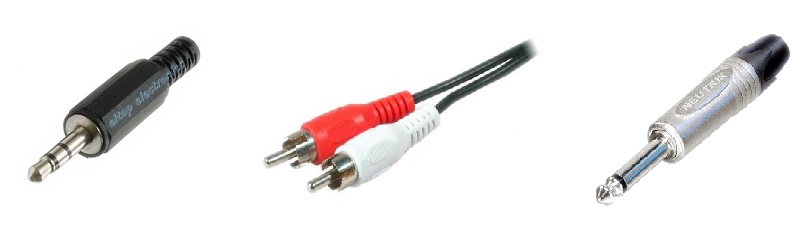
From left to right : A 3.5mm mini-jack, a pair of Cinch (RCA) and a Mono 6,35mm Jack.
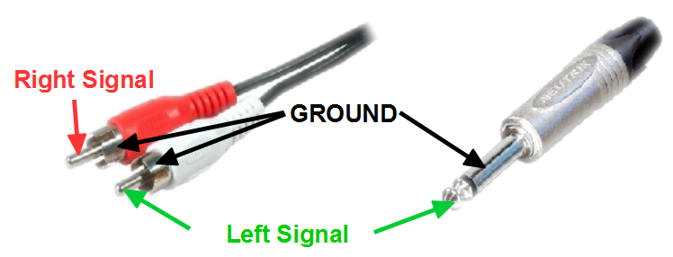
All the RCA to Stereo Jack, Mono Jack to Mono Jack, RCA to RCA, etc. are unbalanced cables, whose wiring is as follows :
The mini-jack is stereo, it has 3 connections, and its connections are shown below :
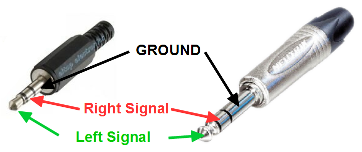
Because they have 3 pins, the stereo cables can be confused with TRS (balanced) ones. In general, the manufacturer of the cable indicated on the product if it is a TRS (balanced) or Stereo (unbalanced) cable.
You got it, you can recognize a balanced or unbalanced cable by the number of connectors that it has (2) !
Balanced audio link
Balanced analog audio links are often in professionnal audio. We can find them very often with XLR to XLR, JACK TRS to XLR, JACK TRS to JACK TRS cables.
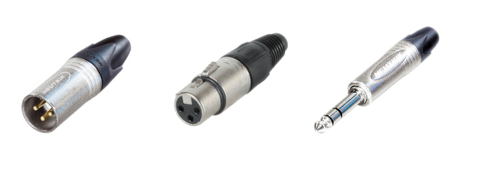
From left to right, a male XLR connector, a female XLR connector, a male TRS Jack.
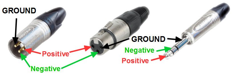
We can recognize, at first sight, a connector that can be used for balanced link to the number of pins it has (3). The wiring is as follows ;
How does a balanced link works ?
The Balanced, or “TRS” is called like this because we transmit the signal two times, in fact, not really, but to simplify, let’s say this ! This is why we need one more cable, and that the link needs 3 cables instead of 2 for the unbalanced link.
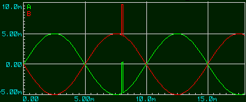
On the emitter side, we transmit the “usefull” signal on the “positive” cable, also called “Hot point” and the signal is inverted before being transmitted on the “Negative” wire, also called “Cold point”. The second signal is transmitted in inverted phase.
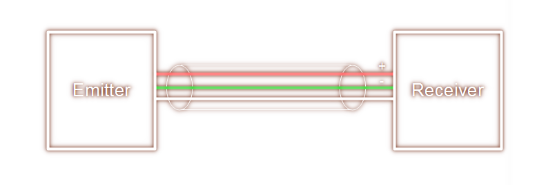
If we visualize the two signals that are tranmitted in a balanced link, we would have the following :
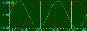
On the receiver side, we will “un-balance”, that means substract the signal on the “Negative” wire from the signal of the “Positive” wire. To illustrate by a small calculation we can imagine that we need to transmit a signal of value 2. The transmitter will transmit +1 on the “positive” wire and -1 on the “negative” wire, the receiver will make the following operation : (+1) – (-1) so 1 + 1 = 2.
Why is balanced link usefull ?
The interest is mainly in the fact that it reduces the noise induced in the cables. In fact, it often happens that disturbances gets added to the “usefull” signal in audio cables and so, with a balanced link, we can simply remove them !
What happens when a parasite gets added to the signal that we want to transmit, is that is gets added the same way on the two cables (it doesn’t know that we transmit the signal in a symmetrical way).
If we visualize the signal that is on the two cables, it look like this :
Then, and as explained before, the receiver is in charge of “un-balance” and by this process, will remove the parasite that has been induced during the transmission !
We can take again the simplified calcuation that we’ve made before. Let’s say we want to transmit a signal of value 2. The transmitter will send +1 on the positive wire and -1 on the negative.
During the transmission, there is a parasite, that adds +0.5 on both signals.
The receiver therefore receives 1+0.5 (so 1.5) on the positive and -1+0.5 (so -0.5) on the negative. When it “un-balance”, it does 1.5 – (-0.5) and gets the value of 2. The parasite has therefore no effect on the transmission.
How to choose ?
The balanced link permits a reduction of the noise, but how do you know if it’s really usefull in your case ?
It depends on multiple factors, between them :
Length of the cables
If the cables are less than one meter long, I don’t think it makes a big difference. A general rule is the shorter the cables are, the less chance there is to get parasites induced on the signals.
Power cables nearby
If power cables are mixed or pass nearby the analog audio cables, it is better to use a balanced link, to reduce the induced noise.
Electro-magnetic environment
If your asymetric link cables are close to power blocks, transformers, or any other source of electro-magnetic radiation, it is very possible that if you change for a balanced link, you will reduce the parasitic noise.
Balanced / Unbalanced conversion
It is obviously possible to change from a connector that is designed for a balanced link (XLR for example) to a connector that is design for an unbalanced link (RCA or Cinch for example). In this case, the link will become unbalanced.
If you want to make this yourself, here are some tips, but you can also buy a dedicated cable !
Balanced input , Unbalanced output
To connect a balanced input to an unbalaned output, you just have to connect the “cold point” from the input to the ground of the connector of the unbalanced output.
Unbalanced input, Balanced output
To connect a balanced output to an unbalanced input, you juste have to remove the connection from the “cold point”. Therefore, there will only be two wires between the grounds and the “hot points”.
Thanks for reading, I hope that this article was usefull !
🙏 If you liked it, please share on your social networks 🙏
And if you have any remark, an experience to share, or if you want to tell me wich subject you’d like for the next article :
Don’t hesitate to share in the comments below !